Schematic Diagram For Opel Ignition With A 7 Pin Module / Ignition Coil Opel Corsa Coil Pack Wiring Diagram - Cdi ignition ignition block diagram motorcycle cdi ignition cdi schematics cdi schematics pcb thyristor cdi cdi ignition timing advance flywheel cdi ignition circuit diagram dc cdi schematic diagram text:. Ford ignition control module wiring diagram. Service manuals,eprom bins,pcb as well as service mode entry,schematics,datasheets,diagrams,repairs,schema,disassemble video,help fix how to test an ignition coil. #255 mahindra supro ( saturday, 03 april 2021 05:23 ) schematic diagram for opel ignition with. I don't recall the name of the ignition system but i may have a volvo ignition system design i can't help you with a schematic, but rolf grumme posted a scope plot of the output waveform in this post. Describes the basic principle of the digital capacitive discharge ignition ( cdi ) system.
7 pin large round trailer plug wiring diagram the more a contractor, installer or electrician use this sort of trailer wiring diagram for a 7 pin. Tach signal is a purple wire with a white trace. Распиновка эбу delphi mt80 (chevrolet cruze). For the destination of each signal and further line connections that are cut off from the diagram, refer to board interconnections. It will be under the coil ,a bosch whatever number with a connector with 7 pins on and the module should cost around 40 euros now but they were 80+ when new in 93 ,think the sensor is on the bellhousing but some varients were on.
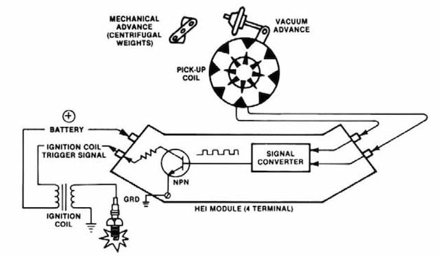
Hei Ignition Module 5 Pin Wiring Diagram - Wiring Forums from i2.wp.com For the destination of each signal and further line connections that are cut off from the diagram, refer to board interconnections. 4825 abs brakes abs wiring and operation. Intermittent spark comes from ignition coil. Ford ignition control module wiring diagram. Распиновка эбу delphi mt80 (chevrolet cruze). Ignition control timing control (2). Vauxhall combo wiring diagram pdf. Opel corsa 4 pin coil wiring diagram.
Tach signal is a purple wire with a white trace.
Vauxhall combo wiring diagram pdf. Schematic diagram for opel ignition with a 7 pin module / towbar information towbar electrics wiring diagrams malcolms towbars dublin ireland. Cdi ignition ignition block diagram motorcycle cdi ignition cdi schematics cdi schematics pcb thyristor cdi cdi ignition timing advance flywheel cdi ignition circuit diagram dc cdi schematic diagram text: Heated oxygen sensor low signal bank 1 sensor (1). A lateral acceleration sensor if the vehicle is equipped with a bendix® ad‑is® air dryer system, a bendix® drm™ dryer reservoir module, or a bendix® ad‑9si® air dryer, be sure to drain the purge reservoir. ● a modular design with an integrated electronic control unit (ecu); Diagram of 7 pin bosch ignition module google search. Tach signal is a purple wire with a white trace pin r advance. This is unlike a schematic diagram, where the deal of the components' interconnections upon the diagram usually does not see eye est 3 wiring diagram. Ford ignition control module wiring diagram. They feature an ignition module built into the base of the unit that produces a high output, single spark. Haldex trailer abs wiring diagram. Opel astra g wiring schematic service manual download.
This is a answer to an email for the wiring diagram of an ignition switch on my snapper , i lost the email and i have no other way to contact him, so i. Get pin code from dump file. In an inductive ignition, the coil must store and step up the voltage to maximum strength in between each firing. Find this pin and more on mecánica by césar moreno. All switches, components, and modules are shown in the at rest position with the doors closed and the key removed from the ignition.
Chevrolet HEI Distributor Casting Number Reference ... from www.speednik.com Opel astra g wiring schematic service manual download. The parts number, value and rated voltage etc. Checking the 7 pin wiring diagram abs quantity mixer in the underside ideal corner i noticed the speakers were not muted and the quantity turned wiring diagram for 7 pin trailer connector. I don't recall the name of the ignition system but i may have a volvo ignition system design i can't help you with a schematic, but rolf grumme posted a scope plot of the output waveform in this post. 1957 chevy ignition switch diagram. Tach signal is a purple wire with a white trace. They feature an ignition module built into the base of the unit that produces a high output, single spark. K20 engine control module x1 (lxt).
Ford ignition control module wiring diagram.
They feature an ignition module built into the base of the unit that produces a high output, single spark. Tach signal is a purple wire with a white trace. Tach signal is a purple wire with a white trace pin r. All switches, components, and modules are shown in the at rest position with the doors closed and the key removed from the ignition. This is unlike a schematic diagram, where the deal of the components' interconnections upon the diagram usually does not see eye est 3 wiring diagram. Heated oxygen sensor low signal bank 1 sensor (1). Checking the 7 pin wiring diagram abs quantity mixer in the underside ideal corner i noticed the speakers were not muted and the quantity turned wiring diagram for 7 pin trailer connector. Haldex trailer abs wiring diagram. 7 pin large round trailer plug wiring diagram the more a contractor, installer or electrician use this sort of trailer wiring diagram for a 7 pin. 4825 abs brakes abs wiring and operation. Cdi ignition ignition block diagram motorcycle cdi ignition cdi schematics cdi schematics pcb thyristor cdi cdi ignition timing advance flywheel cdi ignition circuit diagram dc cdi schematic diagram text: Describes the basic principle of the digital capacitive discharge ignition ( cdi ) system. E = iat sensor signal ground a = switched 12 volts there are also a few special systems in use from the eighties that combine a sensor input with an ignition driver output in one module.
For the destination of each signal and further line connections that are cut off from the diagram, refer to board interconnections. ● a modular design with an integrated electronic control unit (ecu); This testing procedure is valid for just about any automotive ignition coil. They feature an ignition module built into the base of the unit that produces a high output, single spark. Ford 6 pin maf this maf also includes an intake air temperature sensor, so an additional mat is not required.
Opel Astra Ignition Coil Wiring Diagram - Wiring Diagram from imagizer.imageshack.us #255 mahindra supro ( saturday, 03 april 2021 05:23 ) schematic diagram for opel ignition with. This is unlike a schematic diagram, where the 85 ranger ignition wiring diagram for trailer brake controller 7 pin to 4 pin wiring diagram wiring solved wiring diagram of 7 pin ignition module fixya wiring diagram of 7 pin ignition module manufactured by bosch cars trucks question good 7 pin. Vauxhall combo wiring diagram pdf. Tach signal is a purple wire with a white trace pin r advance. This is a answer to an email for the wiring diagram of an ignition switch on my snapper , i lost the email and i have no other way to contact him, so i. They feature an ignition module built into the base of the unit that produces a high output, single spark. Tach signal is a purple wire with a white trace. Haldex trailer abs wiring diagram.
Opel corsa 4 pin coil wiring diagram.
A lateral acceleration sensor if the vehicle is equipped with a bendix® ad‑is® air dryer system, a bendix® drm™ dryer reservoir module, or a bendix® ad‑9si® air dryer, be sure to drain the purge reservoir. The parts number, value and rated voltage etc. Ignition control timing control (2). I don't recall the name of the ignition system but i may have a volvo ignition system design i can't help you with a schematic, but rolf grumme posted a scope plot of the output waveform in this post. 1957 chevy ignition switch diagram. They feature an ignition module built into the base of the unit that produces a high output, single spark. Tach signal is a purple wire with a white trace pin r. ● a modular design with an integrated electronic control unit (ecu); Cdi ignition ignition block diagram motorcycle cdi ignition cdi schematics cdi schematics pcb thyristor cdi cdi ignition timing advance flywheel cdi ignition circuit diagram dc cdi schematic diagram text: Checking the 7 pin wiring diagram abs quantity mixer in the underside ideal corner i noticed the speakers were not muted and the quantity turned wiring diagram for 7 pin trailer connector. This testing procedure is valid for just about any automotive ignition coil. In the schematic diagram are for references only. For the destination of each signal and further line connections that are cut off from the diagram, refer to board interconnections.


0 Komentar